Prelude
In the last post, I started by linking to the various resources and buying the basics and then testing the 'air' by getting the motors to run. In this post I will share my experience in building my own frame.
The frame
Since the BLDCs and ESC are OK tested at this point, I wanted to start with the frame. A look online and those carbon fibre frames are beautiful. Unfortunately, they are also very expensive and for those who know me, I get an allowance that keeps my shopping habits in control. Hence the next best thing is to build one. Easier said than done, what do I build with? I have a lot of scrap wood lying around so that would be my material of choice. But before we start we need instructions or atleast some design rule with which to work.
Using google, I found these.
- http://blog.oscarliang.net/build-a-quadcopter-beginners-tutorial-1/
- http://www.pylo.si/news/236/quadcopter-project-homemade-frame
- http://www.instructables.com/id/Cheap-Sturdy-1-Hour-Quadcopter/
- http://copter.ardupilot.com/wiki/advanced-multicopter-design/
The interesting stuff is the dimensions. I was not able to find the exact theory behind the frame design but I did get an idea of what could be right. Here is a drawing from the above links
[caption id="attachment_1009" align="aligncenter" width="300"]
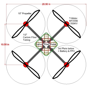 Quad10X1[/caption]
I am using 10 inch props so this could have been used as is. But I increased the distance between props from 10.5in to 16in. This was because I wanted to give the electronics a little more room an wanted to experiment with larger frame dimensions. In my mind, if I increase the inter prop distance, I will gain manuverability- sensitivity to small changes in prop RPMs (newton's levers right?) On the other hand, I will loose stability. Thats OK since I am going to experiment and if I find it to be too unstable, I can always shorten the arms.
With that, I took some scrap wood and sandwiched the joints in plywood in the center. The result is...
[caption id="attachment_1010" align="alignnone" width="300"]
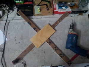 Quadcopter Frame 1[/caption]
The motors needed to be mounted hence a bit of drilling was necessary. I also made some sinks for the shaft of the motors. Applicable for this case but may not be necessary for all motors.
[caption id="attachment_1011" align="alignnone" width="300"]
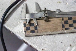 Measuring The Gap[/caption]
[caption id="attachment_1012" align="alignnone" width="300"]
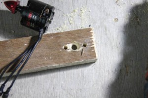 Counter Sink Drilled[/caption]
[caption id="attachment_1013" align="alignnone" width="300"]
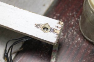 Fitted and Checked[/caption]
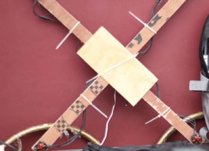
[caption id="attachment_1015" align="alignnone" width="300"]
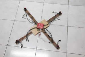 Fitted[/caption]
Some zip ties and we have the ESC in place.
[caption id="attachment_1014" align="alignnone" width="300"]
 Zipped[/caption]
Thats good. Now I need some landing gear. For that I had some 8in PVC pipes in the scrap. So I cut some rings out and stuck them to the arms of the quad. The result is easier to understand...
[caption id="attachment_1016" align="alignnone" width="300"]
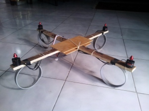 Frame Complete[/caption]
With that we have a frame. I did take test electronics and mount them on the frame then wired a long wire to a pot and tried to see if it could lift. Here is the result.
[embed]https://www.youtube.com/watch?v=cDGiwpPfgfE[/embed]
No comments:
Post a Comment