Abstract
OK im not putting up the exact plans on how to make this robot, but I am putting up the important information and some points where to take care. I finally got this robot up and running but there is a lot of room for improvement. It took me a long time to actually get this together andworking because I have the habbit of exploring and documenting every problem that I come across. In the end the desire to 'finish this thing on and move on' was what actually helped me complete the robot to this extent.
I dealt with the whole thing in phases and thats how I am documenting my work. My official presentation and report are not going to be available online. So for those who either attended my lecture, demonstration or training session, you can contact me regarding help but no spoon-feeds.
Phase 1: Chassis Selection
I started with deciding the chassis for my robot. There are so many good options for the robot chassis. I could have made one myself by using aluminium or wood like my chassis design project, but I found a ready made chassis with a gearbox and DC motors. I took a small crane toy from the market and took out the plow extention and left the necessary plastic on the top part. The bottom and gearbox I left intact because skid-style steering is my favourite design. I thought I could use all four wheels but I did run into some problems later on when I finally tested its movement.

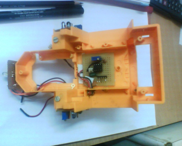
The Image on the right is the image of the Basic Chassis with the Battery Mounted where the operator was sitting.
I had already decided that I was gonna use TSOP1738 sensors for the right and left sensors. I was planning to use ATMEGA8L for the controller so I had an inbuilt ADC to play with. This was a good idea for a more later stage. I will talk about this later. So with the help of an ADC I could easily interface a Sharp GP2D sensor.
But right now I needed to put it on a mobile platform. Instead of using an adaptor to power the robot and just do a "proof of concept" kind of thing, I wanted to make this an actual robot with all the problems addressed. Including... the battery and regulator.
I toyed with the power supply problem a lot. I did not want to use the 7805 voltage regulator for two reasons:
- The 78xx series regulators clamp the output voltage to a fixed value by basically dissipating extra energy as heat hence have lower efficiency.
- They require greater input voltages so as to provide regulated voltages e.g. for 7805 to produce 5v regulated, it requires an input of 7v to operate properly.
I wanted to use rechargable Ni-MH battery packs- each of 1.2v * 4 = 4.8v. With two such battery packs, I had a number of options.
- I could use one battery pack for the controller and one for the TSOP and motors. But this meant that I had a maximum of 4.8v at any given time. Hence I could not use a motor driver IC like L293 or L298D. I could only use an H-Bridge formed out of transistors or MosFETs.
- I could use the battery packs in series and use a switching regulators like MAX638. These switching regulators have an efficiency of around 77%- 90%.
- I could simply use a 7805 with 2 battery packs.
 Option 1 was a good one and I chose to go with it. The switching regulators are comparatively expensive and I was not sure about the availability. The battery packs fit in quite comfortably. So I was happy with what I had. But later on, I decided to go for option 3 because the H-Bridge transistors I used(TIP122) had their own voltage drop greater than what I had intended for the motors. So I ended up using an L298DL298D is really easy to interface with the microcontroller. The H-bridges I made out of TIP122 darlington transistors produced different voltages for the motors because the base resistances and individual temperates all accumulated upto a lot of variables. I simply did not go through all those adjustments. because this way I got a regulated 5v for the controller and the voltage I needed for the motors and also the
 I made a single PCB for a 555 based 38KHz wave generator. I made small sub PCBs in the shape that was available in between the wheels on each side.
Phase 2: The H-Bridge

Since I had decided to use two different battery packs initially, I made 2 idenitical H-bridges from TIP122 transistors but since I was not getting the results I wanted, instead of going through with MOS-FET based H-bridges I went for the L298D. I did experiment with the transistorised h-bridges, but using them was causing me loose the same amount power for which I did not want to use a regulator. With the L298D I was free to concentrate my efforts on other things.
Phase 3: The Controller
 I had planned to use the ATMEGA8L for the final robot but I wanted to do my intial testing with a controller that I was faimliar with. I suggest some of my students use a PC parallel port and it is a really good idea as well because you are programming in C and the cost goes down since you are not spending on a microcontroller or a programmer.
I did most of my design work using a prototyping AT89C52 card I had made for myself. I had made my own Microcontroller programmer for the AT89C52 thanks to resources from the internet. Instead of programming in assembly that would become useless as soon as I changed controllers, I chose to write test programs in embedded C and used the trial version of Keil microvision 3 tool.
So now I had a controller(with PCB) and programmer and a complier to easily do my software work. I made myself another PCB with a CPLD and an ATMEGA8L but more on that in some different project.
Phase 4:
Basic Tests
 I started basic testing by writing simple programs like flexing out the motors. Then I added the sensors and everything worked fine. The videos and pictures are available. Since I had no sensors in the front, I needed to add one. The intial tests went well and the robot worked as far as I can say. Neither the regulator nor the L298D heated as I expected and all tests went well. My mother was exceptionally happy to see the little toy started to run around everytime she tried to pick it up.
Phase 5: The obstacle avoidance robot
The purpose of this project was to design a multi purpose robotic platform where I and others could easily test algorithms as well as test sub modules like battery monitor etc. The robot can be converted into a line follower, a collision avoidance system, a color finder, a photovore, a micromouse or a wall follower. I wrote a simple code that would make this robot a basic obstacle avoidance system. I am not interested in following up with more experiments on this model though. Extra Features I designed some extra feature that I am afraid I will never use. The most significant one is the opto interrupters. Opto Interrupters: I cut small slots in the front wheels and installed opto-interrupters so that I could count the number of steps each side took. This way i could take care of course correction in case one of the two motors turned fasted than the other. I dont want to experiment more because I want to start work on a newer chassis which employs the acerman steering.
No comments:
Post a Comment