Introduction
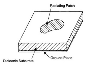
[caption id="attachment_284" align="alignright" width="300" caption="Basics Of a radiating Patch Antenna"]
 [/caption]
The concept of microstrip radiators was first proposed by Deschamps in 1953. A patent was issued in France in 1955 in the names of Gutton and Baissinot. However, 20 years passed before practical antennas were fabricated. Development during the 1970s was accelerated by the availability of good substrates with low loss tangent and attractive thermal and mechanical properties. Improved photolithographic techniques, and better theoretical models. The first practical antennas were developed by Howell and Munson. Since then, extensive research and development of microstrip antennas and arrays, aimed at exploiting their numerous advantages such as light weight, low volume, low cost, conformal configuration, compatibility with integrated circuits, and so on, have led to diversified applications and to the establishment of the topic as a separate entity within the broad field of microwave antennas.
Microstrip Antenna Configuration
The resonance frequency for the (1, 0) mode is given by

Bandwidth
A CAD formula for the bandwidth (defined by SWR < 2.0) is
[caption id="attachment_285" align="aligncenter" width="300" caption="Equation For Bandwidth Of Rectangular Patch Antenna"]
Element Length And Width
Patch width has a minor effect on the resonant frequency and radiation pattern of the antenna. It affects the input resistance and bandwidth to a larger extent. A larger patch width increases the power radiated and thus gives decreased resonant resistance, increased bandwidth, and increased radiation efficiency. With proper excitation one may choose a patch width W greater than the patch length L without exciting undesired modes. A constraint against a larger patch width is the generation of grating lobes in antenna arrays, and a small patch size might be preferred to reduce the real estate requirements. The patch width also affects cross-polarization characteristics. The patch width should be selected to obtain good radiation efficiency if real estate requirements or a grating lobe are not overriding factors. It has been suggested that 1 < W/L < 2
The patch length determines the resonant frequency.
Sonnet and Matlab
Sonnet Suites Professional is an industry leading full-wave 3D Planar Electromagnetic (EM) field simulation software based on the Method of Moment (MoM) technique which accounts for all coupling and radiation effects from DC to THz. It also takes full advantage of mathematically robust and reliable FFT formulation which avoids time consuming, error prone numerical integration. Both MoM and FFT combined give Sonnet an added assurance that it will give outstanding accuracy every time on problems that have traditionally been difficult to solve. Problems with high dielectric constant, thin dielectric layers and/or small dimensions with respect to the wavelength are handled especially well with Sonnet. Sonnet continues to be an indispensable tool for designers involved in RF/Microwave circuits such as distributed filters, transitions, Low Temperature Co-fired Ceramics, multi-layer RF packages, coplanar waveguides, and antennas. In addition, Sonnet has proven successful in mm-wave designs as well as in EMC and EMI analysis.
Design Process Using Matlab Scripting For Practically Usable Results
The program uses Sonnet or SonnetLite (the free version) to perform electromagnetic simulation on a probe fed, rectangular patch antenna. The design of the antenna is modified between Sonnet simulations. This design modification, simulation cycle is repeated until the antenna performs as intended. This Program Works As Follows:
- The GUI "SonnetAntennaDesignGUI.m" is run.
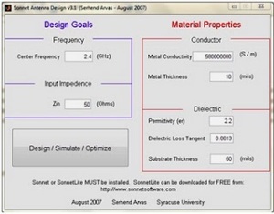
- A GUI prompting the user to enter in the desired antenna performance is initialized.
- Upon entering the data, the main program starts.
- The user is prompted for the location where the desired version of Sonnet is installed on the system.
- An initial antenna design is generated.
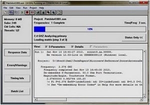
- The design is written to a Sonnet Project File, and Sonnet is invoked.
- After simulation, the antenna performance is gauged, and the design is altered accordingly.
- The new design is resubmitted to Sonnet.
- This process is repeated until the antenna performs as desired.
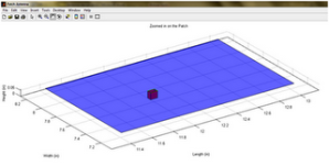
- The performance results are display.
The resulting design can actually be MANUFACTURED. The performance of the antenna will very likely be just as predicted.
Screen Shots
[caption id="attachment_286" align="alignleft" width="300" caption="Screenshot Of Antenna Analyzer Script GUI"]
 [/caption]
[caption id="attachment_287" align="alignright" width="300" caption="The Sonnet window simulating the design"]
 [/caption]
[caption id="attachment_288" align="alignnone" width="300" caption="Design Output- The patch Antenna"]
 [/caption]
Report
I am not including the results because I dont have a very good image right now but the result was very accurate.
Hope this helps.
No comments:
Post a Comment