Sensors 101
A sensor doesn't necessarily mean sight. Some times a sensor is able to pick up much more information like temperature, light, color, velocity, acceleration, inclination, altitude, depth, pressure etc. Depending upon the quantity to be measured and the environment where it will be measured, the sensors will vary. The basic principle however remain the same. Balanced whetstone, conversion techniques etc all are used even in the most advanced sensors. I won't go into the history of things since I expect that my readers have already read the books. I will however explain some basics and assembly of sensors at a more practical level.
Photodiodes and Transistors
A photodiode is...
There is a lot of information out there already so I wont go into the theoretical BG of it. What we need to understand is that the reverse current through the photo diode varies as a function of the light falling in it. So we connect the device in reverse bias. Now how to measure the current? Actually ohms's law[equation 1] does the rest.
V=I x R ... equation 1.
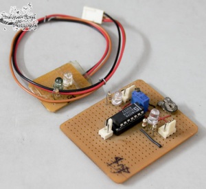
[caption id="attachment_319" align="alignright" width="300" caption="Sensor Circuit using LM324 and IR Leds and Photodiode"]
 [/caption]
Since the current 'I' changes with the incident light, if we pass it through a fixed resistance 'R', then, measure the voltage drop across it, we can 'sense' the amount of light falling. This is the essence of a I-V converter or a current to voltage converter. The circuit below shows that we use an Op-Amp to compare the value of voltage 'V' against a preset value and the Op-Amp will act as a comparator to produce digital values of 0 or 1 hence we have an interface of an analog sensor with a digital output.
I made some for myself initially but since the light from any source will cause output to change so I could not use it everywhere.
The TSOP17xx series receiver
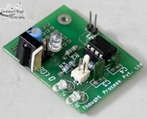
[caption id="attachment_320" align="alignright" width="300" caption="TSOP1738 as sensor with 55 based 38 khz Pulse generator"]
 [/caption]
Thats right. We can use a communications receiver as a sensors. Actually the inbuild filter enables us to filter ambient light, so where the photodiode may fail, the TSOP will prevail. We are required to have a circuit that produces 38Khz if the receiver is TSOP1738 . The schematic for the transmitter and reciever are given below and if your does not work, it means that either you wired it wrong, your power supply does not work or you IR transmitter LED does not work.
The Sharp GP2D
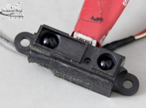
[caption id="attachment_321" align="alignright" width="300" caption="Sharp GP2D Sensor"]
 [/caption]
You won't be getting your hand on this thing very easily. They are the a bit expensive but most good robotic kits have them. The GP2D is a sensor that uses triangulation to determine the distance from the obstacle. Th output is in the form of analog voltage which is a function of the distance being measured.
This essentially means that to use this sensor you will need to interface it with an ADC and then actually calibrate it! Sounds like a lot of work, but the results are really good since it has a good range. But because most people wont be able to afford more than one, there should be a method to reuse this sensors as much as possible. Just like ultrasonic sensors, we can have this sensor mounted on a servo motor- which happens to be expensive in itself. But I would not have mentioned it if I did not have a solution...
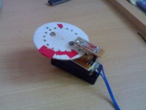
You can try and make a servo motor for yourself by putting a variable resistor with a motor(I will do that if I get the time), or you can have a mount with a slotted disc like I did :) But more on that later...
[caption id="attachment_322" align="alignright" width="300" caption="Home made rotary encoder on a DC Motor"]
 [/caption]

i want to make sensor using photodiodes and lm324. What should be the Vcc and IR emitter's input voltage if we are using a 2.2k resistor with it ?
ReplyDeleteThe circuit in the article uses 5V as vcc. You can calculate the resistor value for the desired current according to the data sheet of the device used. In order to increase the range of the tx you can lower the resistor value but it will burn out the led sooner if not immediately.
ReplyDeleteHope that answers your query.